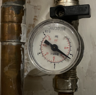
In the middle of a kitchen refit, our central heating (CH) system started experiencing frequent drops in pressure that required refilling for re-pressuring the boiler. Such drops in pressure can be for several reasons, some trivial and some serious and it is important to find the root cause (more on this later). Investigation for the more serious reasons requires professional expertise and expensive tools. Realistically, only airlocks are fixable by the average householder.
As noted above, the manifestation of the problem is a pressure drop leading to the boiler switching off (safety) leading to a cold house and a disgruntled householder.
Faults and the Central Heating System
Reasons for a loss of pressure are attributed to the following categories of causes: (Any simple web search will expose these reasons).
- Boiler faults such as faulty pressure release valves; faulty heat exchanges; faulty expansion vessels, faulty auto air vents.
- Air locks in the system.
- Water leaks such as leaking radiator valves, leaking radiators or leaking pipes.
The CH system is a fairly simple component-based system that can be described by the following UML conceptual model (Figure 1).
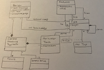
The CH system comprises the following components: The boiler; radiators, a hot water tank, a set of hot water supply taps (for sinks etc) and a pipe network that connects these components. Two start pipes connected to the boiler supply hot water to the radiators and to the hot water tank. A connector (pipe) between two components (e.g. radiator) is conceptually a single pipe but may be composed of a several pipe lengths that are joined. A join is of course, potentially, a source of a leak.
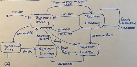
The state of the CH system can be represented by the simple state model of the system shown in Figure 2. The states are important as root cause investigation steps are dependent upon the state of the CH system.
The Tools and Techniques of Leak Detection
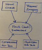
When the Leak Investigation team arrives, they come with a set of tools:
- Thermal imaging cameras for following heat trails.
- Damp detection toolkit.
- Oxygen supply and “Stethoscopes” for listening for air bubbles.
- Hydrogen supply and Gas detection tools.
They also have a specific plan of ordered tasks that requires the heating system to be in specific states. Before arrival, they expect that the heating system is set to run. This is important as they need to map out the routing of the pipes across the residence. In effect they are documenting the system architecture.
They then perform a visual inspection of the system by which they establish the size of the CH system and also look for very obvious leaks. (householder should already have done this before calling out these very expensive people!).
The heating system is then switched off, the boiler isolated and inspected for boiler related leaks (Category 1: Boiler Fault).
They continue with the inspection process by then using the thermal imaging cameras to map out the pipes and locate heat through thermal imaging where it should not be found. They apply a range of heuristics in their analysis based on experience. For example, bigger heat maps are found under wood block flooring than under concrete floors.
Having mapped out the pipe routes, they use the damp detection tools to identify areas of damp, indicate of leaks. Again, heuristics are used to rule out damp not caused by a water leak. A shrub planted adjacent to an external wall will give a damp reading.
The next step is to drain the system completely and pump oxygen (compressed air) into the system and to listen for air being expelled from somewhere in the system.
The last test performed (still while the system is drained) is to pump hydrogen into the CH system and use gas detection tools for locating the leak (s). Importantly, all these tests are probabilistic. They do not give a guarantee of finding a leak.
The probability of finding the leak (s) is about at least two tests confirming a potential leak. Each test on its own includes its own interpretation. So, at best, the tests are aids to professional experiential knowledge which is always hard to formalise.
As it turned out, the Leak investigation team could not confirm the presence of a guaranteed leak. They found a location where there was both damp and thermal heat not consistent with expectations. However, the damp could have been attributed to known problem of a shower cubicle in the vicinity. Given that tiled walls and floors do not help with evaporation, an old leak due to a historical shower failure will still leave damp readings. So there was not sufficient evidence to justify excavation of the area to expose the pipe work. A further issue was also detected with a faulty washer in the drain valve. Their conclusion therefore was to propose leaving the system in a known state and then recording measurements of the pressure status at regular intervals for a period of at least one week.
On Software Testing and Finding Bugs
It should be pretty clear that there are already some clear parallels. But let’s discuss these in more detail.
Documentation
One advantage of modern software practice is that by and large documentation practices have improved significantly so software architecture diagrams and models are readily available or can be re-engineered from the code. Often specific perspectives of architecture may be need to be generated such as dependency graphs, invocation graphs or structural models.
CH systems do not have the luxury of documentation. Each time a change to a CH system is made by a professional plumber, they make the modification and leave no recognisable artifact as a description of what has been done. It is left to the next plumber to interpret the original system, the changes made, and how to attack a new change. If the plumber is lucky, the householder is able to recall prior visits and changes made. Software that has been operational for many years frequently does not have access to such knowledge and so there is a reliance on existing documentation or the ability to generate new documentation (code that has been commented, call graph generation). This decay in knowledge of the working of a system was brilliantly described in Peter Naur’s seminal paper – Programming as Theory Building which applied Gilbert Ryle’s “Theory of Mind” to programming actions. In many ways, each unique visit by a plumber to carry out a maintenance task is the re-construction of the “Theory of the CH System at domestic location X”.
For leak detection, however, engineers (lets call them that), perform a theory building exercise by conducting a visual inspection of the CH system that both builds the theory of the CH system and also analogous to a software engineering team performing code inspections, reviewing architecture documentation and performing executions of the software. These inspections are used to narrow down areas for further experimentation and investigation.
The engineers have one advantage over other plumbers – they have additional tools. They use thermal imaging cameras to support the map-out of the “system architecture” and to allow the CH engineers to construct a theory of the system Notably, the theory of the system remains in the minds of the engineers, no effort is made to document the architecture.
System Decomposition
Component based design, modular programming and other structural techniques lend themselves to isolating software components and developing bespoke testing scenarios. The approach taken by the leak investigation engineers follow their own version of system decomposition.
The visual inspection is very quick to rule out a fault in the CH sub-components that are located on the upper floor of the house, for the simple reason, that water is excellent in leaving a trace due to gravity. And ceilings show such trace very quickly.
System decomposition continues by isolation of the Hot water tank and most importantly, the isolation of the actual boiler which is responsible for its own category of faults. Sub-components of the boiler such as the expansion vessel, heat exchange and air vent element can be easily tested. Thus like software testing, we can easily rule out sub-systems due to the error/fault identified. Also, isolating the boiler and analysing the two “components” separately seems very much like a move from system test to unit test.
System State
Setting a software system to known state, where variables have prescribed / defined values is an important part of fault detection. Leak detection as executed by the engineers in the domestic context follows a similar route. Prior to arrival, it was expected that the CH would be heating the environment. As noted earlier this is essential in order to map the architecture. The CH system is further reset to a known state by draining the system of water. This state allows key tests such as compressed air and hydrogen to be carried out. Tests are done by walking around the CH pipe route and using the stethoscope or testing for escape of Hydrogen test using special equipment. This is equivalent to doing a line by line execution of a program and checking the values of variables. E.g. what is the value of a thermostatic valve of a given radiator? There are also expected values and values that indicate a problem.
Mock Objects
The use of both compressed air and hydrogen testing are reminiscent of mock objects. In object oriented programming, mock objects are simulated objects that replicate the behaviour of real objects as part of a software testing initiative. They are a useful alternative when the real object is slow or does not yet exhibit fault characteristics or where information for test purposes is required. The use of hydrogen and its subsequent detection process there provides an immediate outcome that contributes to the fault analysis.
The Ubiquitous Printf Statement
Classical software bug finding techniques make extensive use of printf statements to output variable values to a terminal window. Such testing techniques support an execution trace and allows multiple variable values to inspected post the execution as opposed to during the execution when using a debugger. There is an approximate analogy to this in both the compressed air tests and the hydrogen escape tests at “variable” points such as thermostatic valves and other known weak points.
Failed Fault Finding
Software bugs such as that due to memory leak errors (if you are still using the C programming language), overwrites of variables, the use of global variables and incorrect initial values do not always manifest themselves as errors in every execution of a programme. Different input values can generate different execution traces through the system so errors need to be externalised. Further, in software, memory leaks usually manifest themselves over a long period of time (hours/days) rather than a single test.
Similarly, a very small “weep” (in the plumber’s vernacular) will not be detected by the tools at the disposal of the engineer but will lead to loss of water pressure which will become visible eventually. During a cold test, however, such a leak would not be identifiable. In such cases, then the only recourse is to leave the system running with an ongoing diagnostic (the pressure gauge) generating data over a period of time.
Conclusion
Experiencing a fault in a critical home system such as a CH system is disabling to the householder. There is a potential for significant damage. This note is really a set of observations of a small ethnographic study of how a professional leak detection engineering team worked deployed tools and techniques to identify faults in a systematic way. It was observed that the approach taken by the engineering team could be denoted as “Root Cause Analysis”. Perhaps more significantly, the methodology of the engineering team demonstrates a fairly equivalent mapping to software debugging practices. As such, the analogy has the potential to be a powerful “real world” example for teaching the principles of software testing.